BUILDING DRAWINGS:
Drawings are made
before any building is built. It is necessary to make drawings of every
building, but the importance of drawing large buildings increases even more. Because
the construction details of small buildings can be mind boggling to a single person.
But it is not enough for one person to keep in mind the construction details of
large buildings. Different people build different parts of large buildings. All
of them must have separate drawings. Regular approval is obtained from the
municipality according to the building boundaries by preparing a drawing of the
building before construction. For this approval, the drawing must conform to
the rules of the relevant municipality. Each municipality has made some laws to
provide a healthy environment to the people. Which is called the BY LAWS of the
institution concerned. A variety of drawings are prepared to clarify the
building's features and dimensions which are as follows.
·
Site Plan
·
Line Plan
·
Detail Plan
·
Foundation Plan
·
Land Scape Plan
·
Elevation
·
Sectional Elevation
·
Perspective Drawing
·
Submission Drawing
·
Model
Site
Plan
This is an sketch in
which different plots for the building are identified. This sketch shows the
plot number of the surrounding houses, the name of the owner, the name of the
street and other important buildings. The site plan describes the width of the
streets and roads in which the house is to be built. The measurement is written
inside the plot. The north-facing map is also marked on this map to make it
easier to find the plot. This drawing is made according to the scale 1 m = 1cm
(1inch = 100 ft ). Only the outer lines of the whole plot are shown in this
drawing. There is no description of the room to be built inside it. Any color
is also given in the total area of the plot. Or sheds are laid so that the
lines will be highlighted in the plot plots.
 |
| Site Plan |
Line
Plan
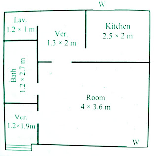
This type of drawing
shows the size and position of different rooms inside the plot. This drawing is
drawn from a single line so it does not show the thickness of the walls.
Actually it makes the drawing architect or engineer. Then with the help of this
drawing the rest of the drawing is prepared which draws the mind. The features
of this drawing are as follows.
·
The measurements given inside the rooms
are internal which does not include the thickness of the walls.
·
The measurements given outside the rooms
are external which includes the thickness of the walls.
·
The first measurement is written
horizontally and the second vertically.
·
This measurement is written in a circle
in a corner of the room to show the height of the room.
·
Doors and windows are displayed in the
relevant place along with the size.
 |
| Line Plan |
Detail
Plan
This type of drawing
shows the size of all the rooms and porches inside the plot and their
arrangement and position. It also shows the thickness of the walls. This plan
is developed with the help of line plan. While preparing this plan, it is
assumed that the entire building has been cut one or two meters above the floor
level horizontally and after cutting, the drawing is prepaid. And in case of
multi-story building, detailed plan of each floor is prepared separately and
each plan is named after that destination. Just as the ground floor is called
the ground floor plan and the first floor above it is called the first floor
plan, so the second floor is called the second floor plan and the floor of the
building in the basement is called the basement floor plan.
After the preparation
of this plan, various facilities like electricity, water and gas warning etc.
are identified in it. Its features are
as follows
·
The plan shows the size and position of
the rooms.
·
The size and location of doors and
windows are indicated and its type is also specified.
·
The location of cabinets and fireplaces
is also clarified.
·
The interior arrangement of the rooms is
also clarified, such as the position of the stove and sinks in the kitchen
instead of the beds, etc.
 |
| Detail Plan |
Foundation
Plan
This type of plan is
made to show the details of the foundations of the building to show the space
and size used in the whole building. This plan is prepared with the help of a
detailed plan in which the walls are laid according to the projection of the
base of the walls parallel to the central line. The characteristics of the
foundation plan that is prepared are as follows:
·
The measurement rooms listed in this
plan are internally measured
·
In this plan, the measurement outside
the rooms is an external measurement of the excavation
·
It also shows the central line of the
walls.
·
It does not show the location of doors
and windows etc.
·
In this plan the width of the walls and
the width of the foundation are shown.
 |
| Foundation Plan |
Land
Scape Plan
In this type of
drawing, apart from the constructed area of the plot, the remaining parts are
shown by decorating it with the help of flower beds, grass plots and other
vines. With the help of this plan the exterior of the house is beautified. A
lot of things are revealed in the preparation of this plan. There is no
separate mark for each item, so each item is displayed alphabetically and a
separate description table is created. This plan includes the following
details.
·
Plot delimitation.
·
Turn north.
·
Built area demarcation.
·
Route to the car.
·
Paths for walking.
 |
| Land Scape Plan |
Elevation
In the elevation a
vertical direction of the building is shown. If the front is shown, this
elevation is called friend elevation. If the building is facing backwards, this
is called back elevation. Similarly, if confessional scenes are done, they are
called side elevation. The scale for elevation is kept according to the
detailed plan. Elevation has the following features
·
The view of the building is displayed
above ground level.
·
In which the length and width and height
of the building are shown.
·
Door and window sizes are also located.
·
The different floors of a multi-story
building are shown together.
·
Internal detail is not displayed in this
scene.
 |
| Elevation |
Sectional
Elevation
The interior details of
the building are displayed in this scene of the drawing.This scene is made by
cutting the building into a vertical plane from the part of the building where
it is necessary to show the details. In this scene, the details are shown from
the base of the building to the parapet. All the same principles that are used
to create the elevation are used to create this scene. If the building is
large, the sections of the building are defined by making more than one
section. The cutting line is laid on a detailed plane at the place where the
cross-section elevation is to be prepared. This cutting line is also laid
straight and if it is necessary to show the details of different places of the
building then the cutting is passed through the required place 90 degree angle
rotating it to. Such a section is called the offset section. Arrow marks are
made in the same direction above the edges of the cutting line in the direction
in which the cut part of the building is to be shown. The features of the
section elevation are as follows:
·
It mentions the details of the premise.
·
It shows the full details of the ground
level, plinth level and floor.
·
Full details of the roof are displayed.
If the roofs are at different levels or of different types, then the
description of the roof is displayed separately.
·
The thickness of the walls are shown and
the doors and windows attached to the walls are also shown cut if they fall
below the cutting line.
·
In front of the cutting line, without
cutting anything, they are shown as elevation.
 |
| Sectional Elevation |
Perspective
Drawing
The shape formed in the
Perspective Drawing is similar to the
image created by the camera. In this drawing, the shape of the body looks the
same as the actual texture of the object. Since the original shape of the body
is visible in this drawing, it can be easily understood even by the common man.
These drawings are usually made for important buildings so that even landlords
or heads of departments can easily understand them, which are often not
technical. To make this drawing, the object is shown with a point, so its lines
are not parallel, but seem to meet at a point. The Perspective drawing has the
following features.
·
The actual measurement of the object is
not displayed.
·
The shape of the object looks exactly
like the shape of the original object.
·
Horizontal axis picture planes appear on
the horizontal.
·
Its horizontal lines of the body appear
to meet at a point called the point of maroon.
·
The vertical axes of the body look
vertical
 |
| Perspective Drawing |
Submission Drawing
Drawings are prepared
before constructing any type of building. This drawing is prepared in
accordance with the rules and regulations laid down by the competent authority
of the area And the drawings prepared for the purpose of obtaining approval
from this authority are called Submission drawings. The competent authority may
be a municipal corporation or a development agency. Submission Drawings include
the following types of drawings and information.
·
Index Plan
·
Detail Plan
·
Elevation
·
Cross-Section
·
Cross Section Of Wall
·
Detail Of Doors And Windows
·
Detail Of Floor
·
Details Of Roof
 |
| Submission Drawing |
vist to more interveiw question
10 CIVIL ENGINEERING BASIC INTERVIEW QUESTIONS AND ANSWERSModel
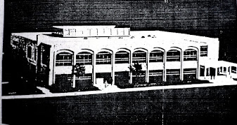
After making drawings
of important buildings, models of these buildings are prepared. This way the
building helps a lot in understanding the research structure. Which predicts
the difficulties encountered during the construction and use of the building. Drawings
are modified to overcome this difficulty. Modeling makes the exterior and
interior detail of the building much clearer. The model has the following
features.
·
The real shape of the building is
visible.
·
The front of the building is noticeably
visible.
·
The interior detail of the building
becomes clear.
·
The common man who cannot understand the
drawings can easily understand the model.
·
Before building an actual building, one
gets an idea of the strengths and weaknesses of the original building.
 |
| Model |
(if you want to lean the full topic relate to bearing capacity then visit to blow link)


0 Comments